How To Test Rectifier On Mercury Outboard
The higher the RPMs the higher the voltage to your battery. Typically the DVA readings for Yamaha and Suzuki will be close to that of Mercury Outboard.
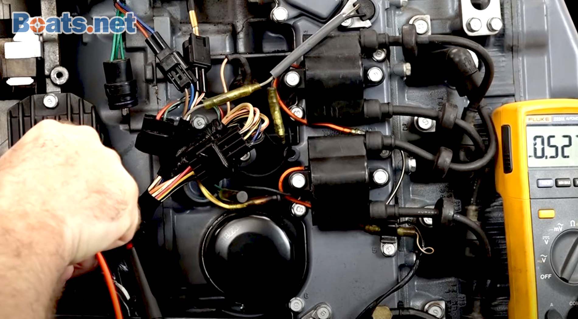
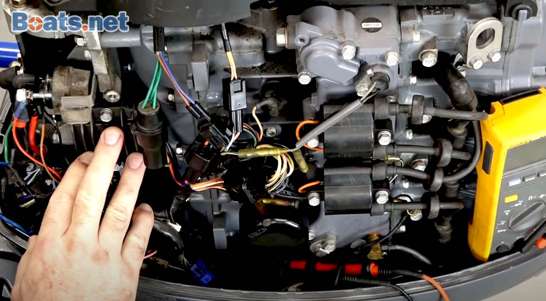
Outboard Motor Regulator Rectifier Testing Boats Net
Mercury produces an extensive line of outboard motors.

How to test rectifier on mercury outboard. Replacing The 100 Voltage Regulator On Outboard Motors With A 4 Mercury Outboard Rectifier Wiring Diagram. The rectifier takes Alternating Current AC from the stator feeds the A and C terminal and converts it to Direct Current DC and outputs the voltage to the B terminal marked with a on both sides. Grn Green WhtGrn WhiteGreen Stripe.
The power that is generated from the alternator is 3-phase AC voltage. Mercury Outboard L3 L4 L6 Rectifier Test - YouTube. The Unit can be used to test points preamp triggers Mercury Outboard battery CD triggers hall effect triggers Alternator driven Ignition triggers and can be used to check injection Pulse from Mercury Outboard EFI modules.
You should have a reading in one direction and none in the other direction. In a C115 the tachometer signal does not come through or from the RR. If the readings are unequal from step 2 then go to step 3.
Start by disconnecting the wires in your bike and switching the multimeter to diode function. A simple test on rectifierregulators except OMC rectifierregulators without cooling fins on the bottom can sometimes be a time-saver. If the rectifier does not blow soon the stator will overheat and melt.
Flip meter leads to opposite leads record again. A quick check is to simply plug in a another new tachometer as a piece of test equipment. Outboard motor electronics are sometimes troublesome particularly since major systems like the power pack may control everything from instrumentation to the timing and synchronization of the motor.
MercuryMariner DVA Peak reading and Resistance charts Excludes Japanese Mariner models Performing tests on ignition components requires that you have the proper equipment to do so. If the rectifier reads anything when testing from colored wires to. Mercury Marine is an international motor boat company based in Lake Forest Illinois providing motors for private commercial and government craft.
If playback doesnt begin. How to test rectifier from a Mercury Marine Force outboard About Press Copyright Contact us Creators Advertise Developers Terms Privacy Policy Safety How YouTube works Test new. This guide even contains recommendations for added materials that you may require in order to complete your assignments.
Or maybe a fuse if there is one will blow first. Mercury Outboard L3 L4 L6 Rectifier Test. If you do this the current from the battery will flow through the rectifier and dissipate as heat in the stator.
But usually boaters dont carry around a spare tach see below. There are two electrical connectors on a regulatorrectifier. Move the negative lead to ground and the positive lead to terminal A.
Turn off the outboard motor and swap the yellow wires around. Measure from red to yellow then reverse your leads. A rectifierregulator is responsible for two separate functions as part of your motorboat jet ski waverunner or marine powersports machines ignition system.
The 650 is an unregulated charging system. Will determine how the regulator rectifier is tested using the diode feature on your meter. The RR is checked for output voltage with the motor running at a fast idle when connected to a fully charged battery.
So to understand why you are blowing the rectifier so often look at your load. Yes it is easy to testConnect your analog meter to positive lead on rectifiers the black to the mounting stud of the diodes Record the test results. As stated previous the traces in a Mercury Outboard Rectifier Wiring Diagram represents wires.
DVA test from each yellow Wire to engine ground. The rectifier youll find most commonly on an outboard is a bridge rectifier and this is the circuit diagram for one of those down here which well go through in a minute so the simplest rectifier you can have is just a single diode that only allows current to flow in one direction so instead of alternating youre simply allowing only go in one direction what this gives you though is half wave rectification. Wiring diagram also provides useful suggestions for projects which may require some extra equipment.
One method requires you to use a multimeter to test the power pack directly. And a black two-terminal connector that sends current out to. Take a look at the positive diode by inserting the positive lead into the bikes positive diode.
The Mercury 650 Outboard will send the meter to 16 volts if you are not careful. Some regulatorrectifiers are easier to test than others and some cannot be tested at all. At times the wires will cross.
If the new tach works properly and the old tach didnt obviously the old tach is faulty. Heres what you need to do to test your rectifier for failure. Output should be 145 volts.
Find the voltage regulator-rectifier on your outboard and grab a good multimeter to test the units inner diodes. Like all mechanical equipment Mercury motors can exhibit issues ignition problems being some of the most. Testing your rectifier is one of the first things you should try if you find that your Voltmeter does not go past the 12 Volt reading even when at high RPMs.
This chart assumes you have the adequate testing equipment to diagnose ignition problems. A faulty rectifier wouldnt damage the tachometer the tachometer simply wouldnt work. On the rectifier test you want to test all wires for continuity in one direction with the red wires.
You can test the Mercury power pack in either one of two ways. Please refer to the lettering in order to follow procedures. The tests involve touching the ground and the touching the posts.
Oh set on 200000 ohm scale. And depending on what brand and model of engine you are working with. A break through by CDIRAPAIR 511-9710 allows you to test most Mercury Outboard Mariner Chrysler triggers and OMCs Quick Start timer bases on the engine.
With the engine running at approximately 1200-1500 RPM. Connect the positive lead of the digital multimeter to the rectifier ground and alternately touch terminals A and C with the negative lead noting the results. However it does not mean link between the cables.
The meter should show continuity between the terminals and the ground. If the results from test 1 and 2 are ok then the stator and regulatorrectifier are ok. 3The easiest way is to mark both side of the connector on the yellow wires that have the lowest voltage.
The RECTIFIER is tasked with converting the 3-phase AC voltage into useable single-phase DC voltage. If no or substandard voltage output then checked the lighting coil for proper input to the RR. You will want to double check the service manual for your engine to ensure the test procedures and wire colors for your engine.
These are usually a gray three-terminal connector that receives current in from the stator. Injunction of two wires is generally indicated by black dot on the intersection of 2 lines. A three-phase regulator-rectifiers diodes take the AC signal that comes out of the engines stator-rotor assembly rectifies it and then smooths it out usually through a capacitor.
Testing Mercury Rectifier Tests Bad Youtube

Buy Regulator Rectifier 815279 3 883072t Voltage Rectifier Regulator For Mercury Mariner Outboard 6 Wire For 883072t Regulator Rectifier Mercury Voltage Regulator Online In Taiwan B08f7gqlbc

Testing A Rectifier Youtube

How To Test Rectifier Outboard Youtube
Outboard Motor Regulator Rectifier Testing Boats Net
Posting Komentar untuk "How To Test Rectifier On Mercury Outboard"