How To Test Mercury Outboard Rectifier
Output should be 145 volts. If the rectifier reads anything when testing from colored wires to.

How To Test Rectifier Outboard Youtube
As stated previous the traces in a Mercury Outboard Rectifier Wiring Diagram represents wires.

How to test mercury outboard rectifier. If playback doesnt begin. The green-white wires from stator are fine. Then leave the volt meter on the battery and start the mtr up and run it long enough to see if your voltage goes up.
A break through by CDIRAPAIR 511-9710 allows you to test most Mercury Outboard Mariner Chrysler triggers and OMCs Quick Start timer bases on the engine. Yes it is easy to testConnect your analog meter to positive lead on rectifiers the black to the mounting stud of the diodes Record the test results. Flip meter leads to opposite leads record again.
Measure from red to yellow then reverse your leads. One method requires you to use a multimeter to test the power pack directly. If it checks out good and your battery voltage goes up when the engine is running the tach is bad.
If you do this the current from the battery will flow through the rectifier and dissipate as heat in the stator. I found a problem between the stator and the rectifier and voltage regulator. Oh set on 200000 ohm scale.
The meter should show continuity between the terminals and the ground. Heres what you need to do to test your rectifier for failure. Injunction of two wires is generally indicated by black dot on the intersection of 2 lines.
Testing your rectifier is one of the first things you should try if you find that your Voltmeter does not go past the 12 Volt reading even when at high RPMs. Or maybe a fuse if there is one will blow first. And depending on what brand and model of engine you are working with.
Dont do this all at one time to give your starter a rest. Mercury Rectifier Testing Steps With Pictures Mercury Outboard Rectifier Wiring Diagram Wiring Diagram includes both illustrations and step-by-step directions that might allow you to definitely really construct your undertaking. Outboard motor electronics are sometimes troublesome particularly since major systems like the power pack may control everything from instrumentation to the timing and synchronization of the motor.
You will want to double check the service manual for your engine to ensure the test procedures and wire colors for your engine. Mercury Outboard L3 L4 L6 Rectifier Test - YouTube. Please refer to the lettering in order to follow procedures.
Put the multimeters positive lead on the positive terminal of the black two-terminal connector. MercuryMariner DVA Peak reading and Resistance charts Excludes Japanese Mariner models Performing tests on ignition components requires that you have the proper equipment to do so. The tests involve touching the ground and the touching the posts.
Start by disconnecting the wires in your bike and switching the multimeter to diode function. If no or substandard voltage output then checked the lighting coil for proper input to the RR. A three-phase regulator-rectifiers diodes take the AC signal that comes out of the engines stator-rotor assembly rectifies it and then smooths it out usually through a capacitor.
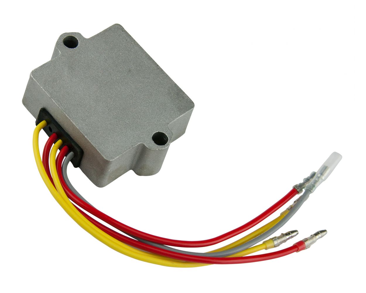
Connect the positive lead of the digital multimeter to the rectifier ground and alternately touch terminals A and C with the negative lead noting the results. The yellow wires coming from the stator to the rectifier are hot and melting at the connectors. You should have a reading in one direction and none in the other direction.
Hope it helps John. This chart assumes you have the adequate testing equipment to diagnose ignition problems. If the rectifier fails it will usually cause the tach to not read.
On the rectifier test you want to test all wires for continuity in one direction with the red wires. The two red wires and grey wire from rectifier are fine. Reverse Bias of Positive Circuit Diodes.
Will determine how the regulator rectifier is tested using the diode feature on your meter. Find the voltage regulator-rectifier on your outboard and grab a good multimeter to test the units inner diodes. There is a test for the rectifier in the FAQ on this site.
You can test the Mercury power pack in either one of two ways. In a C115 the tachometer signal does not come through or from the RR. The 650 is an unregulated charging system.
Another instantaneous way to blow the diodes in the rectifier is to connect the battery up with the polarity wrong. If playback doesnt begin shortly try restarting your device. Mercury Outboard L3 L4 L6 Rectifier Test.
I own a 2001 Bass Tracker-brand boat with a Mercury 60-HP outboard. With this kind of an illustrative guide you are going to be capable of troubleshoot stop and total your projects with ease. Next put the multimeters negative lead on all three terminals of the gray three-terminal connector individually.
Mercury outboard rectifier wiring diagram You will need a comprehensive professional and easy to understand Wiring Diagram. Take a look at the positive diode by inserting the positive lead into the bikes positive diode. The Mercury 650 Outboard will send the meter to 16 volts if you are not careful.
If the rectifier does not blow soon the stator will overheat and melt. That is because the signal is generally shorted to ground. How to test rectifier outboard.
How to test rectifier outboard - YouTube. Grn Green WhtGrn WhiteGreen Stripe. Move the negative lead to ground and the positive lead to terminal A.
The Unit can be used to test points preamp triggers Mercury Outboard battery CD triggers hall effect triggers Alternator driven Ignition triggers and can be used to check injection Pulse from Mercury Outboard EFI modules. However it does not mean link between the cables. The rectifier youll find most commonly on an outboard is a bridge rectifier and this is the circuit diagram for one of those down here which well go through in a minute so the simplest rectifier you can have is just a single diode that only allows current to flow in one direction so instead of alternating youre simply allowing only go in one direction what this gives you though is half wave rectification.
I suspect thats the case. The RR is checked for output voltage with the motor running at a fast idle when connected to a fully charged battery. The higher the RPMs the higher the voltage to your battery.
At times the wires will cross. The rectifier takes Alternating Current AC from the stator feeds the A and C terminal and converts it to Direct Current DC and outputs the voltage to the B terminal marked with a on both sides. Disable your ignition put a voltmeter on your battery and crank the mtr over to run the battery down to about 12 volts.
Mercury Rectifier Testing Steps With Pictures

Mercury Test Part 194 5279 815279 New Jetskiplus Z 2 194 5279 Test

Mercury Outboard L3 L4 L6 Rectifier Test Youtube

Testing Mercury Rectifier Tests Bad Youtube

Testing A Rectifier Youtube
Posting Komentar untuk "How To Test Mercury Outboard Rectifier"